Please note that the recommended version of Scilab is 2026.0.1. This page might be outdated.
See the recommended documentation of this function
AUTOMAT
automata (finite state machine)
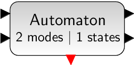
Block Screenshot

Palette
Description
This block gives the possibility to construct hybrid automata, i.e., a hybrid system whose discrete part is defined via modes and transitions between modes, and the continuous part is defined via DAE (differential algebraic equations).
The automaton block provides a switching mechanism between subsystems corresponding to control modes of an automaton. Subsystems are constructed in such a way that they have the state vector as input ( coming from the automaton block) and compute the flow and jump functions (zero-crossing) and pass them back to the automaton block. The state variables are defined in the automaton block and the subsystems are static functions.
Suppose that a hybrid automaton consists of M
control
modes. The continuous-time dynamics in mode is defined with DAE
( ) where
 i is in [1 .. M]
and the dimension
of x is N (N ≥ 0) for any i in [1 .. M]. Suppose that in
control mode i, there are  jump conditions indicating jumps toward other modes. The jump conditions are defined by
functions
  where
where
j is in [1 ..
].
When a jump function changes sign and becomes positive, a mode
transition will happen. When k-th transition function becomes positive, a transition to mode k happens and state vector x is reset to :  for i.e.,
  .
.
In order to develop an automaton containing a mode with multiple reset functions, the value of the current and previous active modes should be used. These values are available at the first output port of the block.
The automaton block has the following input/output ports.
Output 1: The first output port is a vector of size two consisting of the current and the previous active control modes, i.e.,
 .
.Output 2: The second output port is a vector of size
2Nproviding the state vector and its first time derivative, .
.Inputs: The automaton block has
Mvector input ports corresponding toMmodes or subsystems of the automaton. Each input defines the dynamic behavior in the control each mode as well as the reset functions and the transition functions. The input portiwhich is the output of thei-th subsystem is a vector of size2N+ . Each input is composed of the following vector.
The first
Nelements of theInput_iare the continuous-time dynamics. The dynamics of the system in the control modeiis described by a smooth index-1 DAE .
.The next
Nelements ofInput_iare the values used to reset the continuous-time state when a transition to control modeiis activated.The next
Z_ielements ofInput_iare the jump or zero-crossing functions. If thej-th zero-crossing function of modeicrosses zero with negative to positive direction, a transition toj-th destination mode happens.
Event Output: This is an event output port, which is activated whenever a mode transition happens. This event is useful when an event is needed to activate or initialize a part of the subsystem not included in the internal dynamics of the automaton block.
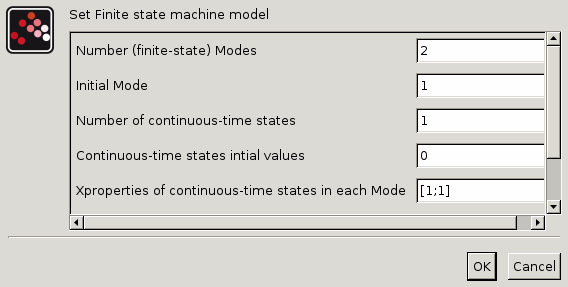
In the interface window, the number of control modes, the initial control mode and the initial value of continuous-time state at the beginning of the simulation should be given.
Dialog box

Number of (finite-state) Modes
Number of modes in the automation.
Properties : Type 'vec' of size [1,1].
Initial Mode
Initial active mode at the beginning of the simulation.
Properties : Type 'vec' of size [1,1].
Number of continuous-time states Number of continuous-time states at modes. Note that the number of continuous-time states is the same in all modes.
Properties : Type 'vec' of size [-1,1].
Continuous-time states initial values
Initial value of continuous-time states at the beginning of the simulation.
Properties : Type 'vec' of size [-1,1].
Xproperties of continuous-time states in each Mode
In this field the state types in mode are given. A state in an index 1 DAE can be either differential state or algebraic state. vector is coded in an M*N matrix, where M is the number of modes and N is the number of states. This matrices indicates whether a continuous-time state is algebraic or differential in each control mode. If in the
i-th mode,j-th state is differential, the(i,j)-th element of the Xproperty matrix should set to "+1", otherwise it should set to "-1". Xproperty can be given as a 1*N vector if type of states remain the same in all modes.Properties : Type 'mat' of size [-1,-1].
Jump from Mode 1:[..;M_final(Guard=In(1).i);..]
The fields express the mode transition information. Suppose that all control modes are labeled from 1 to M. Then, in the field corresponding to control modei , destination modes of modei are defined in a vector.j-th element of this vector gives the destination mode whenj-th jump function :
becomes positive. For example, if in the field of the mode2 , the user defines [1;3;4], it means that in mode2 , there are three active jump functions. When, for example, the third jump function becomes positive, a mode transition to mode4 will be activated.
Properties : Type 'vec' of size [-1,1].
Default properties
always active: yes
direct-feedthrough: no
zero-crossing: yes
mode: no
regular inputs:
- port 1 : size [3,1] / type 1
- port 2 : size [3,1] / type 1
regular outputs:
- port 1 : size [2,1] / type 1
- port 2 : size [2,1] / type 1
number/sizes of activation inputs: 0
number/sizes of activation outputs: 1
continuous-time state: yes
discrete-time state: no
object discrete-time state: no
name of computational function: automat
Interfacing function
SCI/modules/scicos_blocks/macros/Misc/AUTOMAT.sci
Computational function
SCI/modules/scicos_blocks/src/c/automat.c (Type 10004)
References
- "Modeling Hybrid Automata in Scicos", Masoud Najafi, Ramine Nikoukhah, 2007 IEEE. Multi-conference on Systems and Control, Singapore
| Report an issue | ||
| << Demonstrationsblocks_pal | Demonstrations blocks palette | BOUNCE >> |