Please note that the recommended version of Scilab is 2026.1.0. This page might be outdated.
See the recommended documentation of this function
LOGIC
Combinatorial Logic
Block Screenshot

Contents
Palette
Description
This block implements a standard truth table for modeling programming array, digital circuit and any other boolean expressions.
The user must specify a matrix that defines all the possible block outputs in the Truth Table field. In consequence, the number of rows must be a power of two. Each row of the matrix contains a logic combination of input elements.
Setting the parameter Truth Table defines the number of inputs and outputs in the following way :
The number of inputs is defined by the equation:

The number of outputs is equal to the number of columns of the matrix.
This block can be activated by an implicit input event or it can inherit the clock from the regular input (parameter Accepts Inherited Events).
Data types
The block supports the following types :
Input : scalar. All Scilab's integer data type.
A positive input is considered as logical 1, a negative or a null input as logical 0.
Output : same type and dimensions than input.
Dialog box
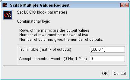
Truth Table
The matrix of outputs. The elements must be 0 or 1. For more information see the description part.
Properties : Type 'mat' of size [-1,-2].
Accepts Inherited Events (0:No, 1:Yes)
Specifies if the clock is inherit or not. 0 or 1
Properties : Type 'vec' of size 1.
Default properties
always active: no
direct-feedthrough: yes
zero-crossing: no
mode: no
regular inputs:
- port 1 : size [1,1] / type 5
- port 2 : size [1,1] / type 5
regular outputs:
- port 1 : size [1,1] / type 5
number/sizes of activation inputs: 1
number/sizes of activation outputs: 0
continuous-time state: no
discrete-time state: no
object discrete-time state: no
name of computational function: logic
Examples
Example 1
The easiest example to consider is the OR example.In this case we have two inputs and only one output. The truth table for this example is :
| input 1 | input 2 | output |
| 0 | 0 | 0 |
| 0 | 1 | 1 |
| 1 | 0 | 1 |
| 1 | 1 | 1 |
and the Truth Table parameter is writing :
[0;1;1;1]
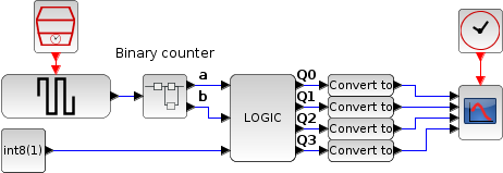
Example 2
This example shows the use of LOGIC bloc as a demultiplexer. The goal is to send the true
constant input on one of the four outputs according to the state of the two selection inputs:
a and b.
The truth table is the following:
| Constant | a | b | Q0 | Q1 | Q2 | Q3 |
| 0 | X | X | 0 | 0 | 0 | 0 |
| 1 | 0 | 0 | 1 | 0 | 0 | 0 |
| 1 | 0 | 1 | 0 | 1 | 0 | 0 |
| 1 | 1 | 0 | 0 | 0 | 1 | 0 |
| 1 | 1 | 1 | 0 | 0 | 0 | 1 |
where X stands for "indifferent".
To set this table in the Truth Table parameter, we can simply write:
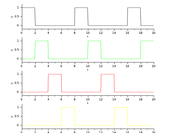
The following figure shows the resulting outputs
Q0
à
Q3
during the simulation when the selection
inputs
a
and
b
are
generated by a binary counter.
Interfacing function
SCI/modules/scicos_blocks/macros/IntegerOp/LOGIC.sci
Computational function
SCI/modules/scicos_blocks/src/c/logic.c
See also
- BITSET — Set a Bit
- BITCLEAR — Clear a Bit
- LOGICAL_OP — Logical operation
- EXTRACTBITS — Bits Extraction
| Report an issue | ||
| << JKFLIPFLOP | Integer palette | SHIFT >> |