DEADBAND
Deadband
Block Screenshot
Contents
Description
The Dead Band block provides a region of zero output.
It's a range of inputs for which the output remains unchanged. Outside that range there is a linear relationship between the deadband input u(k) and the dead band output v(k).
Below is shown a graph of a particular deadband:
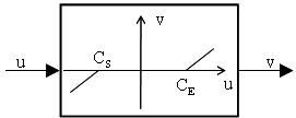
It is defined by:

where
cE > cS
When the input u(k) is between Cs and CE, the output v(k) is zero. When the input is greater than or equal to the upper limit CE, the output is the input minus the upper limit. When the input is less than or equal to the lower limit Cs, the output is the input minus the lower limit.
Parameters
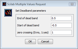
End of dead band
The upper limit of the dead band.
Properties : Type 'vec' of size 1
Start of dead band
The lower limit of the dead band.
Properties : Type 'vec' of size 1
Zero crossing
Select to enable zero crossing detection to detect when the limits are reached.
Properties : Type 'vec' of size 1
Default properties
always active: no
direct-feedthrough: yes
zero-crossing: yes
mode: yes
regular inputs:
- port 1 : size [1,1] / type 1
regular outputs:
- port 1 : size [1,1] / type 1
number/sizes of activation inputs: 0
number/sizes of activation outputs: 0
continuous-time state: no
discrete-time state: no
object discrete-time state: no
name of computational function: deadband
Interfacing function
SCI/modules/scicos_blocks/macros/Misc/DEADBAND.sci
Computational function
SCI/modules/scicos_blocks/src/c/deadband.c (Type 4)
Example
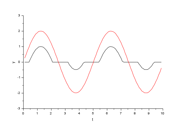
The following is an example of a system with deadband.
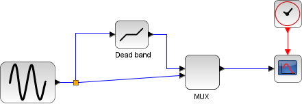
The input is a sine wave. The magnitude is set to 2, the frequency to 1.25 and the phase to 0. The Deadband block has the following parameters:

This plot shows the effect of the dead band on the sine wave.
| Report an issue | ||
| << BACKLASH | Discontinuities palette | HYSTHERESIS >> |